 Scroll through, or use this index for quick navigation:
People involved with this research project...
Importance of this research...
Objectives of this research project...
Results of preliminary studies...
Equipment used in experimental study...
Photos of the progress thus far...
Movie of base excitation of multi-level structure...
Companies providing equipment and support for this work...
Site info including author's e-mail and snail mail addresses... Scroll through, or use this index for quick navigation:
People involved with this research project...
Importance of this research...
Objectives of this research project...
Results of preliminary studies...
Equipment used in experimental study...
Photos of the progress thus far...
Movie of base excitation of multi-level structure...
Companies providing equipment and support for this work...
Site info including author's e-mail and snail mail addresses...
|
People involved with this research project...
Mark Whorton, NASA Marshall Space Flight Center, Advisor
Goodarz Ahmadi, Clarkson University Dept. of MAE Professor, Advisor
Jeffrey T. Shimmel, Clarkson University Dept. of MAE Graduate Student
|
Importance of this research...
The increase of space flights and the future space station has made a new low gravity
environment accessible to the science community. Potential scientific research uses of
the microgravity environment include crystal growth, critical point viscosity measurements,
protein growth and tissue culturing, fluid physics and transport phenomena, as well as many
other experiments.
While there is much interest in using the microgravity condition for scientific experiments, the
environment on-board the shuttle has been found to be exposed to many undesirable vibration
excitations. The bandwidth of these excitations is from very low frequency - less than 0.001 Hz,
to around 30 Hz. The very low frequency accelerations are in the microgravity range whereas
the accelerations above 0.01 Hz are several orders of magnitude above the microgravity level.
The undesirable vibrations above the microgravity level, the so-called g-jitter, affect the
performance of various other science experiments. Most earlier studies of passive and active
vibration control strategies were directed towards protection of the flexible space structures.
Comparatively, little attention was given to low amplitude (and low frequency) vibration control
of sensitive scientific equipment aboard spacecraft. With an active control system, ambient
acceleration levels on the isolation platform can be educed to about I mirco-g in the 0.1 to 10 Hz
bandwidth.
This study is concerned with sensitivity analysis of scientific equipment to orbital vibration
environment, as well as with developing a practical and effective vibration control technology
for microgravity application. Computer simulations and laboratory experiments will be used to
provide the needed understanding of the sensitivity typical scientific devices and to test the
effectiveness of vibration control strategy.
|
Objectives of this research project...
One of the main objectives of this research work is to gain a fundamental understanding of the
degree of sensitivity of the equipment that is used in delicate (scientific) flight experiments in
the orbital vibration environment. The other main goal is to develop a practical and effective
microgravity vibration control strategy. The specific objectives are the following:
To provide an understanding of the sensitivity of experimental flight hardware to microgravity
loading including g-jitter vibrations.
To develop a practical design for an effective vibration control strategy for space applications.
To construct an experimental model for laboratory experimentation.
To develop passive, active and hybrid vibration control strategies with use of smart materials
such as (piezoelectric and shape memory alloys).
To analyze the experimentally obtained data and to assess the vibration sensitivity and performance
of the control devices.
|
Results of preliminary studies...
This is in progress.
|
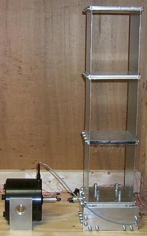
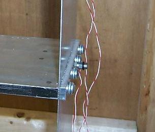
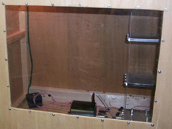
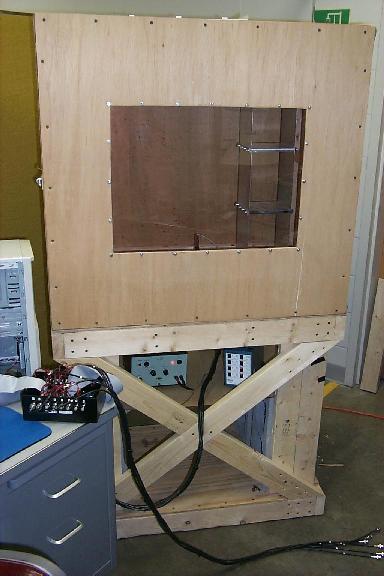
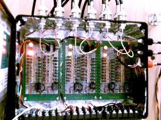
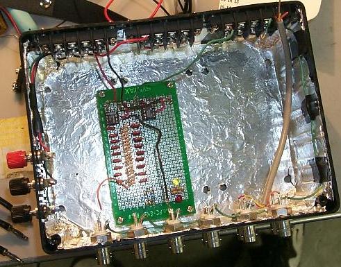
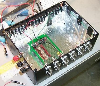
Equipment used in experimental study...
The equipment used in this research project was either donated, purchased, or built here at Clarkson
University in the vibrations lab or in the undergraduate machine shop. All of these components can be
seen in the photos listed below.
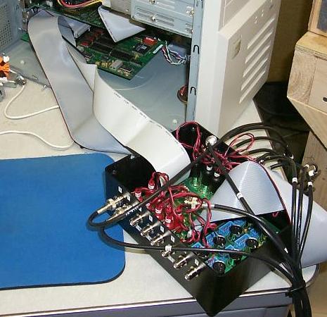
The MultiQ-3 AD/DA Board is a general purpose data aquisition and control board made up of 8 analog inputs
and 8 analog outputs. The system is accessed through the PC bus and has a separate terminal board on which all
of the connections to the board can be made. (This was supplied by Quanser Consulting)
WinCon is a real-time Windows 95/98/NT application that runs Mathworks Simulink generated code using the
Real Time Workshop on a PC. WinCon consists of a client and a server and this software can be run on various
setups ranging from 1 PC to an entire network of PCs. (This was supplied by Quanser Consulting)
The accelerometers used are Piezoelectric and are powered by simple, inexpensive, constant-current signal
conditioners. These sensors are easily placed into systems having a fixed voltage sensitivity, low per channel cost,
and low-impedance output. (These were supplied by PCB Piezotronics)
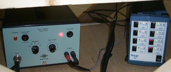
The accelerometer power supply is an 8-channel singal conditioner with a selectable gain from 1x, 10x, to
100x. This unit is a line-powered, 8 channel digitally controlled amplifier that provides constant-current excitation
to up to 8 transducers. (This was supplied by PCB Piezotronics)
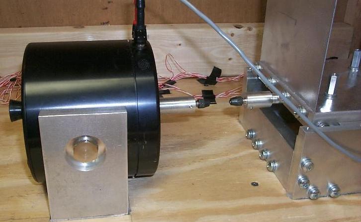
The vibration exciter is a versatile instrument that operates in the frequency range of 10Hz to 20kHz with a maximum
obtainable bare table frequency with assisted air cooling of 100 g's, and a maximum of 60N of force. (This was supplied
by Brøel & KjŹr)
The power amplifier for the vibration exciter has a maximum of 75VA and is switchable between 1.8A and 5A. It has
low distortion over a wide frequency range and a built in attenuator with variable gain control and along with sensors to
detect heat build up as well as clipping in the signal. (This was supplied by Brøel & KjŹr)
|
Movie of base excitation of multi-level structure...
This is in progress.
|
Companies providing equipment and support for this work...
Quanser Consulting Advanced Teaching Systems
Brøel & KjŹr Sound & Vibration
PCB Piezotronics


|
Site Info...
This site was last updated on July 29, 1999 and is maintained by:
Jeffrey T. Shimmel
Clarkson University
Department of MAE
P.O. Box 5725
Potsdam, NY 13699-5725
|
|


