
 |
Scheme
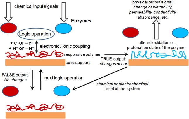
showing the general concept of interfacing enzyme-based logic systems
with signal-responsive polymers operating as “smart” chemical actuators
controlled by the gate output signals. M. Pita, S. Minko, E. Katz, Enzyme-based logic systems and their applications for novel multi-signal-responsive materials. Journal of Materials Science: Materials in Medicine 2009, 20, 457-462. |
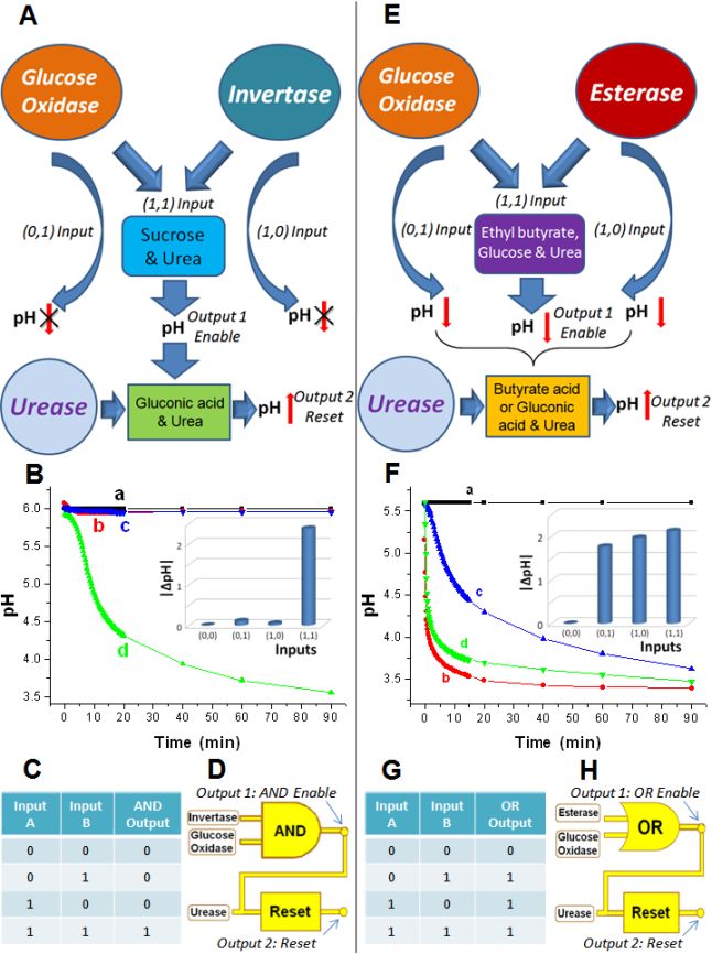 |
Enzyme logic gates producing pH changes
for coupling
with pH-switchable polymers Biochemical logic gates with the enzymes used as input signals to activate the gate operation: the absence of the enzyme is considered as “0” and the presence as “1” input signals. The Reset function was catalyzed by urease. (A) The AND gate based on GOx and Inv catalyzed reactions. (B) pH changes generated in situ by the AND gate upon different combinations of the input signals: a) “0,0”, b) “0,1”, c) “1,0” and d) “1,1”. Inset: Bar chart showing the pH changes as the output signals of the AND gate. (C) The truth table of the AND gate showing the digital output signals corresponding to the pH changes generated upon different combinations of the input signals. (D) Equivalent electronic circuit for the biochemical AND-Reset logic operations. (E) The OR gate based on GOx and Est catalyzed reactions. (F-H) The same as (B-D) for the OR gate. The enzyme logic gates shown here were
used to switch the states of the membrane, nanoparticle assembly and
emulsion shown in the next table.
 The enzyme logic gates were studied by PhD student Jian Zhou. I. Tokarev, V. Gopishetty, J. Zhou, M. Pita, M. Motornov, E. Katz, S. Minko, Stimuli-responsive hydrogel membranes coupled with biocatalytic processes. ACS Appl. Mater. Interfaces 2009, 1, 532-536. M. Motornov, J. Zhou, M. Pita, I. Tokarev, V. Gopishetty, E. Katz, S. Minko, Integrated multifunctional nanosystem from command nanoparticles and enzymes. Small 2009, 5, 817-820. M. Motornov, J. Zhou, M. Pita, V. Gopishetty, I. Tokarev, E. Katz, S. Minko, “Chemical transformers” from nanoparticle ensembles operated with logic. Nano Lett. 2008, 8, 2993-2997. M. Pita, S. Minko, E. Katz, Enzyme-based logic systems and their applications for novel multi-signal-responsive materials. Journal of Materials Science: Materials in Medicine 2009, 20, 457-462. S. Minko, E. Katz, M. Motornov, I. Tokarev, M. Pita, Materials with built-in logic. J. Comput. Theor. Nanoscience 2011, in press. |
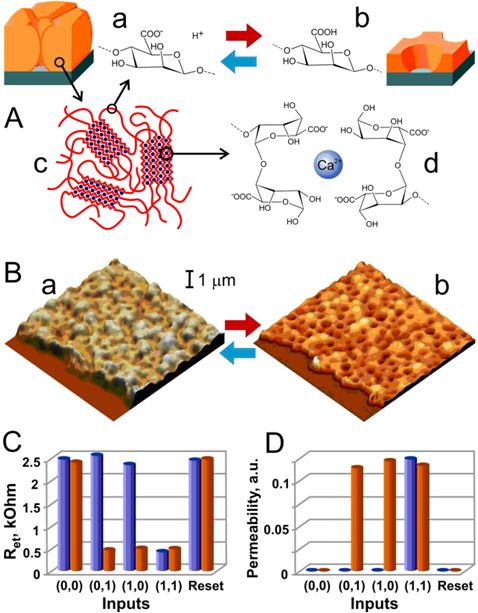 Signal-responsive membrane coupled with the enzyme-based logic gates |
Materials with Built-in Logic
Nanostructured signal-responsive materials were coupled with a combination of enzyme-based biocatalytic chemical reactions to yield information-processing responsive hybrid materials with built-in Boolean logic. The combination of enzymatic reactions performed AND/OR logic operations, transducing biochemical input signals into macroscopic structural changes of the materials, thus resulting in the amplification of the biochemical signals. The information-processing hybrid materials could be scaled up to biocomputing networks composed of many logic gates mimicking biological systems and effectively processing complex biochemical information, resulting in reversible changes of macroscopic structures and allowing adaptation of materials to environment changes. I. Tokarev, V. Gopishetty, J. Zhou, M. Pita, M. Motornov, E. Katz, S. Minko, Stimuli-responsive hydrogel membranes coupled with biocatalytic processes. ACS Appl. Mater. Interfaces 2009, 1, 532-536. M. Motornov, J. Zhou, M. Pita, I. Tokarev, V. Gopishetty, E. Katz, S. Minko, Integrated multifunctional nanosystem from command nanoparticles and enzymes. Small 2009, 5, 817-820. M. Motornov, J. Zhou, M. Pita, V. Gopishetty, I. Tokarev, E. Katz, S. Minko, “Chemical transformers” from nanoparticle ensembles operated with logic. Nano Lett. 2008, 8, 2993-2997. M. Pita, S. Minko, E. Katz, Enzyme-based logic systems and their applications for novel multi-signal-responsive materials. Journal of Materials Science: Materials in Medicine 2009, 20, 457-462. S. Minko, E. Katz, M. Motornov, I. Tokarev, M. Pita, Materials with built-in logic. J. Comput. Theor. Nanoscience 2011, in press. |
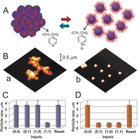 Signal-responsive nanoparticles coupled with the enzyme-based logic gates |
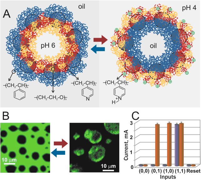 Signal-responsive emulsion coupled with the enzyme-based logic gates |


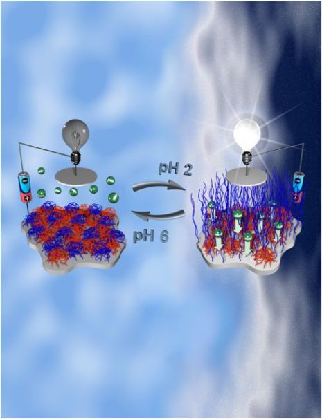 Artistic view of the
polymer-functionalized interface switchable by pH signals (design of
Dr. Tokarev)
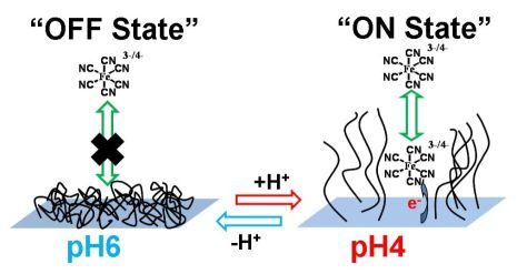 Scheme of the polymer-functionalized interface switchable by pH signals and applied for the controlled electrochemistry of a diffusional redox probe. |
Switchable
electrode controlled by enzyme logic network system: Approaching
physiologically regulated bioelectronics
The logic network composed of three
enzymes (alcohol dehydrogenase, glucose dehydrogenase and glucose
oxidase) operating in concert as four concatenated logic gates
(AND/OR), was designed to process four different chemical input signals
(NADH, acetaldehyde, glucose and oxygen). The cascade of biochemical
reactions culminated in pH changes controlled by the pattern of the
applied biochemical input signals. The “successful” set of the inputs
produced gluconic acid as the final product and yielded an acidic
medium, lowering the pH of a solution from its initial value of pH 6-7
to the final value of ca. 4. The whole set of the input signal
combinations included 16 variants. Those that corresponded to the logic
output 1, according to the Boolean logic encoded in the logic
circuitry, resulted in the acidic medium. The pH changes produced in
situ were coupled with a pH-sensitive polymer-brush-functionalized
electrode, resulting in the interface switching from the OFF state,
when the electrochemical reactions are inhibited, to the ON state, when
the interface is electrochemically active. Soluble [Fe(CN)6]3–/4–
was used as an external redox probe to analyze the state of the
interface and to follow the changes produced in situ by the enzyme logic
network, depending on the pattern of the applied biochemical signals.
The chemical signals processed by the enzyme logic system and
transduced by the sensing interface were read out by electrochemical
means (cyclic voltammetry and Faradaic impedance spectroscopy). This
readout step features a “sigmoid” processing of the signals that
provides “filtering” and significantly suppresses errors. Coupling
between signal processing enzyme logic networks and electronic
transducers will allow future “smart” bioelectronic devices to respond
to immediate physiological changes and provide autonomous
signaling/actuation depending on the concentration patterns of the
physiological markers.
M. Privman, T.K. Tam, M. Pita, E. Katz, Switchable electrode controlled by enzyme logic network system: Approaching physiologically regulated bioelectronics. J. Am. Chem. Soc. 2009, 131, 1314-1321. |
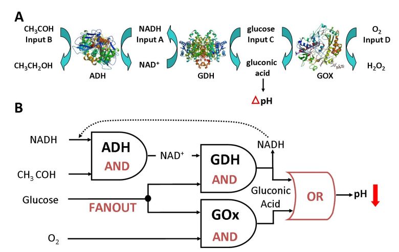 The biocatalytic cascade used for the
logic processing of the chemical input signals and producing in situ pH
changes as the output signal. (B) The equivalent logic circuitry for
the biocatalytic cascade.
|
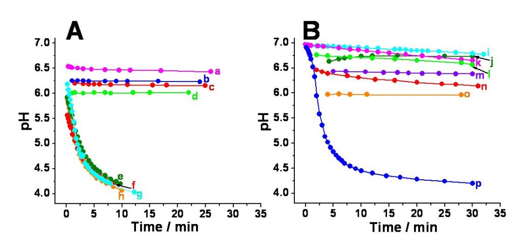 pH Changes generated in situ by the enzyme logic
network: (A) Variation of pH with time for the oxygenated solutions
upon application of various combinations of the chemical input signals
A, B, C, D: a) 1,1,0,1; b) 1,0,0,1;
c) 0,0,0,1; d) 0,1,0,1;
e) 1,0,1,1; f) 0,1,1,1;
g) 1,1,1,1; and h) 0,0,1,1.
(B) Variation of pH with time for deoxygenated solutions upon
applications of various combinations of the chemical input signals A,
B, C, D: i) 0,0,1,0; j) 0,0,0,0;
k) 0,1,1,0; l) 1,1,0,0;
m) 1,0,0,0; n) 1,0,1,0;
o) 0,1,0,0; and p) 1,1,1,0.
All solutions contained alcohol dehydrogenase (ADH), glucose
dehydrogenase (GDH), and glucose oxydase (GOx), 10 units•mL-1
each, dissolved in 0.1 M Na2SO4. Input A was 0.5
mM NADH, input B was 5 mM acetaldehyde, input C was 12.5 mM glucose,
and input D was dissolved oxygen in equilibrium with air.
|
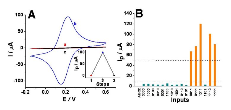 (A) Sample cyclic voltammograms obtained
for the ITO electrode modified with the P4VP polymer brush in: a) the
initial OFF state, pH ca. 6.7, b) ON state enabled by the input
combination 1,1,1,0, recorded at pH ca. 4.3, and c) in situ reset to the OFF state, pH
ca. 8.8. Inset: step 1 – maximum current of the anodic feature recorded
for the initial OFF state, step 2 – anodic peak current for the ON
state, and step 3 – maximum current of the anodic feature after a reset
to the OFF state. Deoxygenated unbuffered solution of 0.1 M Na2SO4,
10 mM K3Fe(CN)6, and 10 mM K4Fe(CN)6
also contained ADH, GDH, and GOx, 10 units•mL-1 each. Input
A was 0.5 mM NADH, input B was 5 mM acetaldehyde, and input C was 12.5
mM glucose. Potential scan rate, 100 mV•s-1. (B) Anodic peak
currents, Ip, for the 16 possible input combinations. Data
were obtained from cyclic voltammograms recorded under the same
conditions as those in Figure (A). The dotted lines show threshold
values separating logic 1,
undefined and logic 0 output
signals.
|
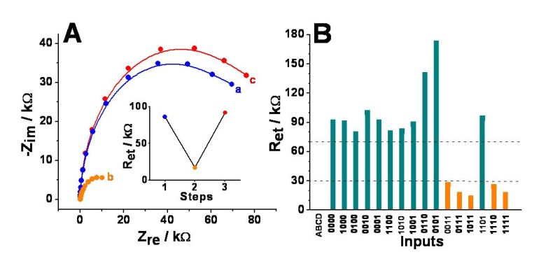 (A) Sample impedance spectra (in the form
of Nyquist plots) for: a) the initial OFF state, pH ca. 6.5, b) ON
state enabled with the input combination 1,1,1,1,
recorded at pH ca. 4.0, and c) in
situ reset to the OFF state, pH ca. 8.8. Inset: step 1 – the Ret
of the initial OFF state, step 2 – Ret for the ON state, and
step 3 – Ret for the reset to the OFF state. Unbuffered
solution of 0.1 M Na2SO4,10 mM K3Fe(CN)6,
and 10 mM K4Fe(CN)6 also contained ADH, GDH, and
GOx, units•mL-1 each. Input A was 0.5 mM NADH, input B was 5
mM acetaldehyde, input C was 12.5 mM glucose, and input D was dissolved
oxygen in equilibrium with air. (B) Electron transfer resistance, Ret,
for the 16 possible input combinations. Data derived from impedance
spectra obtained under the same conditions as those in Figure (A). The
dotted lines show threshold values separating logic 1, undefined and logic 0 output signals.
|