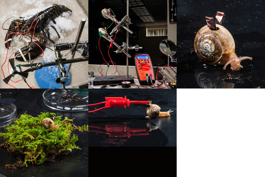
 |
Two movies prepared in
our lab showing the experiments with the
biofuel cell implanted in a snail: Video
clip 1; Video clip 2. You can also find additional video and audio clips here. They are available in English, German, Russian and Hebrew. |
 |
Two movies prepared in
our lab showing the experiments with the
biofuel cell implanted in a snail: Video
clip 1; Video clip 2. You can also find additional video and audio clips here. They are available in English, German, Russian and Hebrew. |
 |
Implantable biofuel cells suggested as
sustainable micro-power sources operating in living organisms are still
exotic and very challenging to design bioelectronic systems. Very few
examples of abiotic and enzyme-based biofuel cells operating in animals
in vivo have been reported. Implantation of biocatalytic electrodes and
extraction of electrical power from small living creatures is even more
difficult and has not been achieved yet. We are reporting on the first
implanted biofuel cell continuously operating in a snail and producing
electrical power over long period of time using physiologically
produced glucose as a fuel. The “electrified” snail, being a
biotechnological living “device” was able to regenerate glucose
consumed by biocatalytic electrodes, upon appropriate feeding and
relaxing, and then produce a new “portion” of electrical energy. The
snail with the implanted biofuel cell will be able to operate in a
natural environment producing sustainable electrical micro-power for
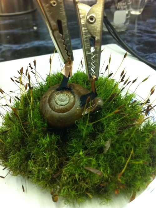
activating various bioelectronic devices. Photo of a snail with implanted biocatalytic electrodes connected with crocodile clips to the external circuitry (close view). L. Halámková, J. Halámek, V. Bocharova, A. Szczupak, L. Alfonta, E. Katz, J. Am. Chem. Soc., 2012, 134, ASAP article, DOI: 10.1021/ja211714w |
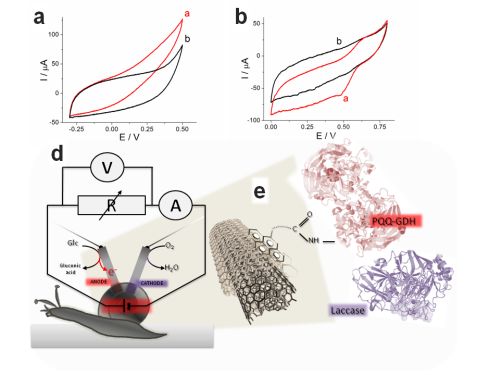 |
Cyclic voltammograms of the PQQ-GDH-anode:
curves a and b in the presence and absence of 20 mM glucose,
respectively. b. Cyclic voltammograms of the laccase-cathode: curves a
and b in the presence and absence of O2, respectively. All
cyclic voltammograms were obtained in
vitro in a solution composed of 22 mM NaHCO3, 40 mg∙mL-1
BSA, 6.7 mM MgCl2, 5 mM KCl; pH 7.4; scan rate 1 mV∙s-1.
c. The implanted biofuel cell circuitry. d. Coupling of the enzymes
with CNTs via the bifunc-tional linker PBSE. |
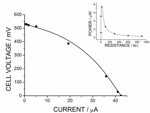 |
Polarization curve of the implanted
biofuel cell operated in vivo. Inset: Power generated on a variable
load resistance. |
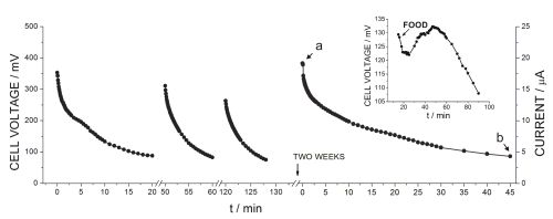 |
Voltage
generated by the implanted biofuel cell operated in vivo on 20 kΩ load
resistance as a function of time. Inset: Restoring the cell voltage in
real time upon feeding the snail. |
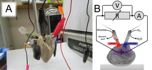 |
(A)
Photo of a clam with implanted biocatalytic electrodes (close view).
(B) Circuitry schematics showing the external variable load resistance
connected to the clam-biofuel cell for measuring voltage and current
produced in vivo. |
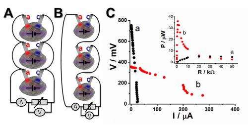 |
(A)
and (B) Circuitries composed of 3 clam-biofuel cells connected in
parallel and in serial, respectively. (C) Polarization curves of the
living batteries composed of 3 clam-biofuel cells connected in serial
(a) and parallel (b) operating in
vivo. Inset: Power generated on a variable load resistance for
the serial (a) and parallel (b) battery connections. |
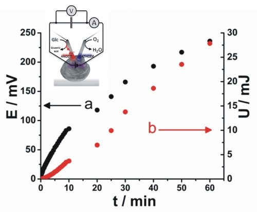 |
Charging
of a 1 F capacitor (voltage and energy vs. time) from a battery
composed of 3 clam-biofuel cells connected in parallel. The inset is a
schematic illustration of the circuitry where only one biofuel cell
connected to the capacitor is shown for simplicity. |
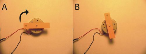 |
Photos
of an electrical motor rotating upon connection to the capacitor
charged from the living battery composed of three clam-biofuel cells.
(A) and (B): The initial and final positions of the rotor; note the
clockwise rotation direction. |
